


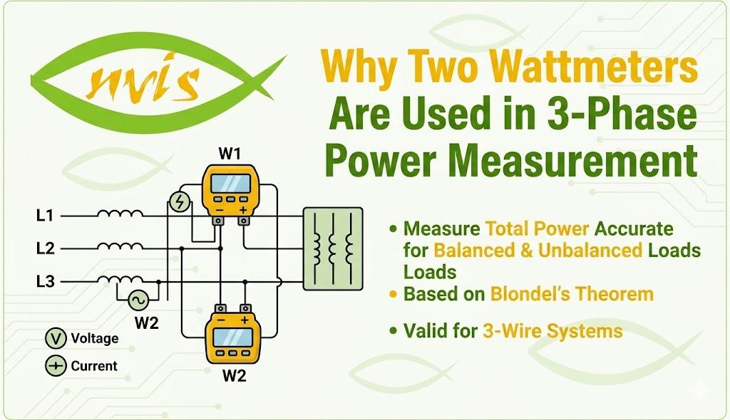
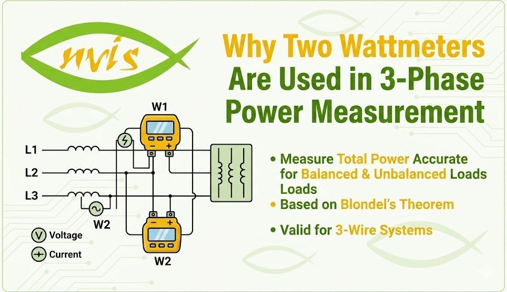
TL;DR The two wattmeter method is a practical, mathematically proven technique for measuring total power in a 3-phase, 3-wire system using only two instruments. This blog explains the science behind it, how Blondel's Theorem justifies it, how wattmeter readings are interpreted, and why it remains the go-to method in industrial electrical engineering.
-
For electrical engineering students, technicians, and practicing engineers in India - this blog explains why exactly two wattmeters (not one, not three) are used to measure power in a 3-phase, 3-wire system.
-
One wattmeter cannot capture the complete power picture of a 3-phase system, and three wattmeters are unnecessary for a 3-wire configuration.
-
Blondel's Theorem provides the mathematical foundation - for a system with N wires, only N-1 watmeters are needed to measure total power.
-
The two wattmeter method works for both balanced and unbalanced loads, in both star (Y) and delta connections, and can also reveal power factor from the readings alone.
-
The algebraic sum of both wattmeter readings gives total 3-phase active power - and in some load conditions, one wattmeter may even read negative, which is expected and accounted for.
What Is the Two Wattmeter Method and Why Does It Matter?
When you're working with industrial electrical systems in India, 3-phase power is everywhere. From factory motors to transformer substations to CNC machines, almost all heavy equipment runs on a 3-phase supply.
Measuring the power consumed in these systems isn't as straightforward as single-phase setups. You can't just hook one wattmeter across one line and call it done.
That's where the two wattmeter method comes in. It is used to measure the total active power in a 3-phase, 3-wire system, whether the load is balanced or unbalanced, using just two single-phase watmeters.
It's elegant, it's accurate, and there's solid mathematical reasoning behind why two is exactly the right number. Let's unpack that.
Blondel's Theorem: The Science Behind the Number
The question "why two wattmeters?" has a precise answer, and it traces back to French electrical engineer André Blondel.
According to Blondel's Theorem, when power is supplied by a K-wire AC system, the number of wattmeters required to measure power is one less than the number of wires, i.e. (K-1), regardless of whether the load is balanced or unbalanced.
Apply this to a standard 3-phase, 3-wire setup: K = 3, so you need K-1 = 2 wattmeters.
Blondel's Theorem states that if a network is supplied through N conductors, the total power is measured by summing the readings of N wattmeters so arranged that a current element of a wattmeter is in each line and the corresponding voltage element is connected between that line and a common point. If the common point is located on one of the lines, then power may be measured by N-1 wattmeters. This means a 3-phase, 3-wire system requires only two single-phase wattmeters.
This is not a shortcut or an approximation. It's a mathematically exact result. The third wattmeter would add no new information because the power in the third line is already implicitly accounted for by the other two.
Three wattmeters are required to measure power in a 3-phase, 4-wire system, whereas only two wattmeters are required to measure power in a 3-phase, 3-wire system. The three wattmeter method is employed specifically for the 3-phase, 4-wire configuration.
How the Connection Is Made
Understanding the method requires knowing how the two wattmeters are physically connected in the circuit.
In this method, the current coils of the two wattmeters are inserted into any two of the three lines, for example lines A and C. The voltage (pressure) coils of both wattmeters are then referenced to the third line (line B).
Each wattmeter has a current coil (CC) and a pressure coil (PC). In a star-connected load, it is optional to connect the neutral point. In a delta-connected load, connections need not be opened to connect the wattmeters.
This makes the two wattmeter method highly practical on the shop floor. You don't need to dismantle the load or rewire the star point. You simply insert the instruments into two of the three lines and read the values.
How Total Power Is Calculated
Once connected, the total 3-phase power is straightforward to compute.
The total instantaneous power in the three-phase circuit is the sum of the instantaneous powers in each phase. The two wattmeter method cleverly measures this total power by taking the algebraic sum of the readings of the two wattmeters.
So the formula is simply:
P = W1 + W2
For a balanced three-phase star-connected load, the individual wattmeter readings work out as:
-
W1 = VL × IL × cos(30° - φ)
-
W2 = VL × IL × cos(30° + φ)
Where VL is line voltage, IL is line current, and φ is the phase angle of the load.
When you add W1 and W2, the result simplifies to the total 3-phase active power: P = √3 × VL × IL × cosφ.
What Happens When One Wattmeter Reads Negative?
This is a scenario that trips up students and junior engineers all the time on Indian university exams and in practical labs.
When the phase angle φ is greater than 60°, (30° + φ) exceeds 90°, and cos(30° + φ) becomes a negative quantity, making the reading on wattmeter W1 negative. To get a positive indication, the connections to either the current coil or the voltage coil must be reversed, and the power measured by the wattmeter must be recorded as a negative quantity.
This isn't a measurement error. It's physically meaningful. The algebraic sum (W1 + W2) still gives you the correct total power. When subtracting the negative reading, you're essentially capturing the reactive nature of the load.
Some special conditions worth knowing for exams and practicals:
-
Unity power factor (cosφ = 1, φ = 0°): Both wattmeters read equal positive values.
-
Power factor = 0.5 (φ = 60°): One wattmeter reads zero, the other carries the full load reading.
-
Power factor below 0.5 (φ > 60°): One wattmeter deflects in the negative direction.
Finding Power Factor Using the Two Wattmeter Method
A major advantage of the two wattmeter method is that it doesn't just give you active power. When this method is used to measure the power dissipated in a balanced load, the power factor of the circuit can also be determined from the meter readings alone.
The formula for power factor angle φ is:
tan φ = √3 × (W1 - W2) / (W1 + W2)
And the power factor = cos φ.
Reactive power can also be derived from wattmeter readings. The reactive power Pr = √3 × (W1 - W2), where W1 and W2 are the individual wattmeter readings.
This means a single measurement setup gives you active power, reactive power, and power factor, all at once. For energy auditors, maintenance engineers, and quality teams in Indian industries, this is incredibly useful.
The two wattmeter method does not indicate whether the calculated power factor is leading or lagging. This must be determined by considering the load. A largely inductive load has a lagging power factor, and a predominantly capacitive load has a leading power factor.
Where Is the Two Wattmeter Method Used?
This method isn't just a theoretical exercise. It's widely deployed in Indian industrial environments and is a standard measurement technique across sectors.
Common applications include:
-
Motor testing labs - determining input power and efficiency of 3-phase induction motors
-
Power distribution panels - measuring load power in manufacturing units
-
Energy audits - calculating power consumption in factories, textile mills, and pumping stations
-
Transformer testing - verifying input and output power in substation equipment
-
Industrial energy metering - as the principle behind many 3-phase energy meters
For engineering students appearing in GATE, university practicals (BE/B.Tech electrical), or diploma-level exams, understanding this method in depth is non-negotiable.
Two Wattmeter vs One Wattmeter vs Three Wattmeter - When to Use Which
There are three methods for measuring power in a three-phase system: the three wattmeters method, the two wattmeters method, and the one wattmeter method.
Here's how to think about which to use:
One Wattmeter Method: Only valid for balanced loads in a specific star-connected configuration. Not practical for most real-world applications where loads vary.
Two Wattmeter Method: The most practical and widely used. Works for both balanced and unbalanced loads in a 3-wire system, star or delta, without needing access to the neutral wire.
Three Wattmeter Method: Used for 3-phase, 4-wire systems (where a neutral wire is present). Each wattmeter measures one phase, and the readings are summed.
For 99% of industrial 3-phase power measurement scenarios in India, the two wattmeter method is the standard choice.
Conclusion
The two wattmeter method isn't just a convenient shortcut. It's a mathematically exact and practically efficient approach to measuring 3-phase power, rooted in Blondel's Theorem.
Key takeaways from this blog:
-
Blondel's Theorem dictates that a 3-phase, 3-wire system needs exactly (3-1) = 2 wattmeters
-
Total power = algebraic sum of W1 and W2
-
Works for balanced and unbalanced loads, in both Y and delta connections
-
Power factor can be derived directly from the two readings
-
One wattmeter reads negative when power factor drops below 0.5, and that's normal
-
Three wattmeters are needed only for 3-phase, 4-wire systems with a neutral
If you're preparing for university exams, a competitive test like GATE, or working in an electrical maintenance role, mastering the two wattmeter method is one of those fundamentals that never go out of style.
Learn why two wattmeters are used in 3-phase power measurement, how Blondel’s Theorem works, and how total power and power factor are calculated in 3-wire systems.

 English
 Arabic
 French
 Spanish
 Portuguese
 Deutsch
 Turkish
 Dutch
Dutch
 Russian
 Romaian
 Portuguese (Brazil)
 Greek
Greek